[button type=”btn_small” url=”http://tinkernut.com/dvYN6″ target=”” button_color_fon=”#36bf00″ ]FOLLOW THIS PROJECT[/button]
The Raspberry Pi Zero W is an amazing miniature computer piece of technology. I want to turn it into an epic portable Spotify radio that displays visuals such as Album Art. So in this new series called “Tinkernut Workbench”, I show you step by step what it takes to build a product from the ground up.
[slogan h1=”Important Links”]
[ox_list type=”ox_list_animated”]
[/ox_list]
[/slogan]
The first biggest hurdle to overcome is the fact that the Pi Zero (at least at the time of this post) doesn’t have audio output. There are a few different ways to get around that.
- Split out the audio from the HDMI output
- Purchase a digital audio extension: Adafruit MAX98357 or Pi Zero “hat” extension
- Make a simple circuit to extract audio from the GPIO pins
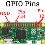
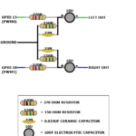
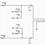
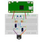
If you go with option 1 or 2, you can skip to step 5, but if you want to make your own custom audio output, continue reading. The Adafruit blog has a fantastic guide for how to make your own PWM audio adapter. And it’s actually surprisingly easy…if you’re not afraid of a soldering iron. The basic idea is to force the audio through the GPIO pins of the raspberry pi. In this case, it’s pins 18 and 13 (and ground). You can see a schematic below for what I’m going to try and accomplish.
- GPIO Pin Layout
- Diagram
- Schematic
And here’s the parts it requiers:
- 2 x 10 µF capacitors
- 2 x 0.33 or 0.01 capacitors
- 2 x 270 Ohm resistors
- 2 x 150 Ohm resistors
- Female 3.5mm audio jack
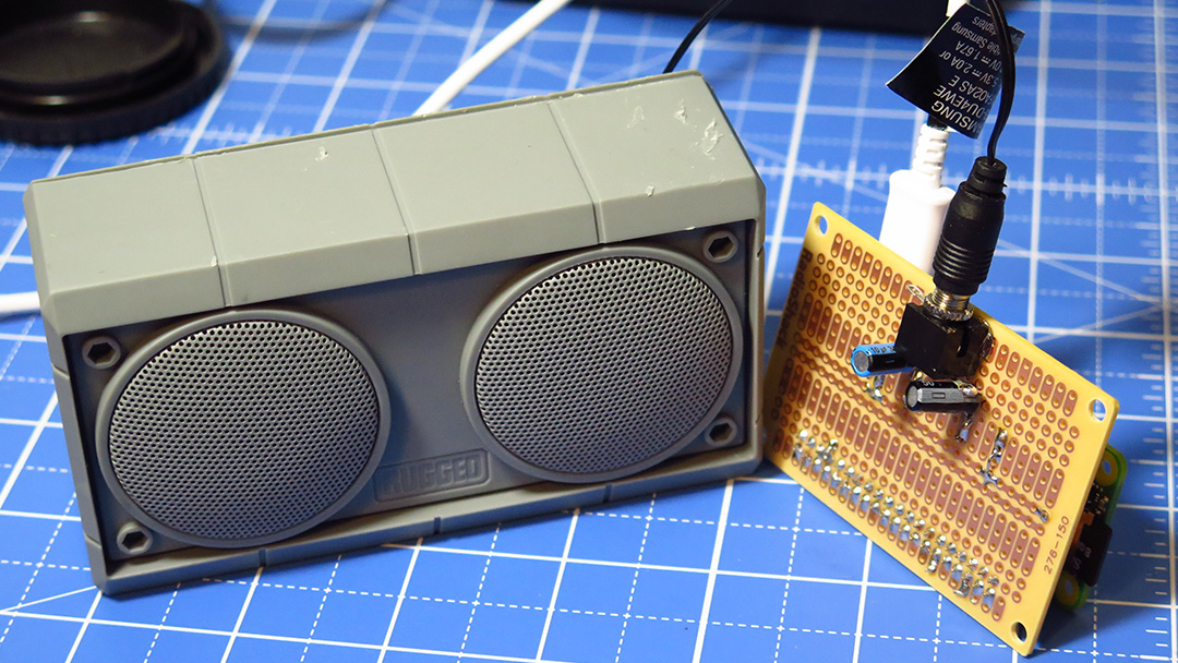
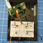
I was able to arrange the components on a bread board and then hooked up a pair of powered speakers for testing.
So to see if this micro-contraption works, we need to tweak the raspberry pi software a little bit. Since we enabled SSH on the raspberry pi, we can login into it remotely from a different computer. On Linux and Mac, you can open up a terminal and just type “ssh pi@192.168.###.###” (replacing # with the static IP you set) and login with your password. On Windows, you’ll need a third party SSH tool. I’m fond of Putty for Windows. Download and install it, then set up a new SSH connection pointing to your Pi’s static IP. Then just login with your password.
We have to tell the Pi to force audio to the PWM pins (Pins 18 and 13), and there are several different methods of doing this, but one of the simplest ways I found was to add a line to the configtxt file:
-
sudo nano /boot/config.txt
-
#add to bottom of file

dtoverlay=pwm-2chan,pin=18,func=2,pin2=13,func2=4
-
ctrl X (to exit) Y (to confirm save)
-
sudo reboot
After rebooting, I now need to force the Raspberry Pi’s audio through the PWM channel. So after reconnecting to the Pi through SSH, type “sudo raspi-config” and go to 7. Advanced Options > A4 Audio > 1 Force 3.5mm. Then save and exit. With the powered speakers on and plugged into the breadboard, and the breadboard plugged into the Raspberry Pi, I can test it all out by playing some audio using this command:
-
aplay /usr/share/sounds/alsa/Front_Center.wav
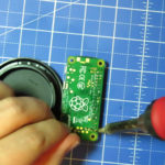
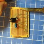
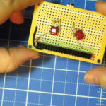
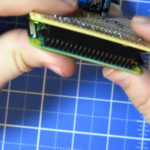
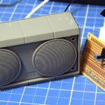
If you can hear audio then everything’s working correctly and we can move everything from the breadboard to a nice, compact circuit board! To make it easy to connect the circuit board to the Pi Zero, I turned the Pi Zero off, disconnected everything, and soldered some header pins to each of the pin ports. Then on the circuit board, I soldered some female header pins so that they could fit together easily. From there I soldered on all my components, fired the Pi back up, and tested it out again to make sure it still worked. Looking good! Now for the Amp!
